It includes the following topics
1. Object of grinding.
2. Metallic wire grinding procedure.
3. Grinding Roller
Object of grinding:
As a card operates, the action of fibres and dirt with it, gradually wear the points of wire causing them to become poor cleaning point. The purpose of card grinding is to maintain the card clothing in a sharp condition.
Metallic wire grinding procedure
Cleaning the card:
Remove the lap and strip the cylinder & doffer
Run the card until all the flats are stripped out
Remove the flat strips
Remove all the trash from under the card for they may cause a fire.
preparing for grinding:
Take off the main belt and guide.
Remove the doffer driving belt and dis engage the doffer driving gear.
Remove the flat driving belt. Br Remove the belt from cylinder to lickerin. - Disengage the calender roller drive,
Remove the doffer comb bands. - Replace the main belt and guide to drive the cylinder back wards (in opposite direction) most motors are fitted with reversing starters and the change of direction can usually be obtained by means of special key.
Connect the cylinder and doffer pulleys with an open belt.
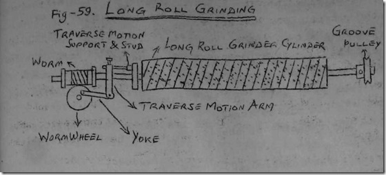
put the grinding roll in the cylinder stand with the driving pulley on the opposite side from the main driving belt.
Put on the grinding band to drive the grinding roll, so that they turn in the same direction as the cylinder. This causes the surface of the emery covered roll to run against the back of the card wire.
In the case of fast grinding, the driving connection is given as shown in the figure, assuming the cylinder speed of 170 rpm then,
Grinding Roll speed = 170 x (18/4) =755
Doffer speed =170 x (18/12) =255 RPM
In the case of slow grinding the following driving connection is given as shown in the fig.
Assuming 170 RPM as the speed of the loose pulley on the cylinder shaft, then Doffer =(170 x(16/95) x (5/100) x (40/216) =13. 2 RPM

Cylinder =13. 2 x (2 / 18) =8. 8 RPM
Grinding roller =170 x (16/9. 5)x (9. 5/4) =680 RPM
Start the card -The card is now so arranged that the cylinder,
doffer and grinding roller are the only parts moving.
Brush out the cylinder very care fully by holding the brush firmly and press it into the wire of the moving cylinder.
Stop the card and lift & correct any bent or jammed wire with special hook.
Before grinding, the setting should be noted so that an indication of amount of wire height removed by grinding can be obtained, when these settings are re-checked after grinding,
DURING GRINDING
Start the card running, listening for contacts. If either grinding roll touches it will cause a brushing sound.
Set the grinding roll down gradually until slightly brushing -action is heard.
The adjusting of the grinding roll during grinding against the cylinder is usually a matter of judgement.
Spark should not exceed 50 mm on cylinder and 30 mm on doffer.
Set the grind stone about 0. 15 mm clear off the surface of the wire at each end of traverse.
After 6-8 min, stop the grinding and the sharpness of wire points should be examined through micros cope. The presence of serrations on the wire and majority of points showing clear grinding, striations with a fine burr at the leading edge can be taken as an indication that the grinding has been done well.
Worn out grinding stone & deep meshing of grinding stone on wire would break or damage the wire and may lead to hooked or bent wire points.
The grinding stone used in grinding a card is aluminium oxide vitrified bond 46/L 7v or WA 80 /PE 31. It is a emery having a granular formation.
Starting up after grinding:
Remove the grinding band and Roller Remove the belt from cylinder to doffer Engage all the card drive connection as usual Reset all the settings Put on the main belt and bring the normal direction to cylinder after grinding. Turn the card parts by hand and listen for any contacts of surfaces. tart the card care fully and listen for contacts
Put the lap and reengage the side shaft gear
Start the calender roll when the web is in good shape.
Discard the first few yards of sliver on account of dirt and light weight.
Grinding Frequency;
Generally, grinding of cylinder and doffer should be carried out once in 6 month or after taking 40000 kg production and card should be reclothed once in 3 to 4 year or after 1. 5 lakhs kg production in one card.
Generally frequency of grinding depends upon the rate of production, quality of material, type of wire points and level of neps in the cad web.


